Main feature
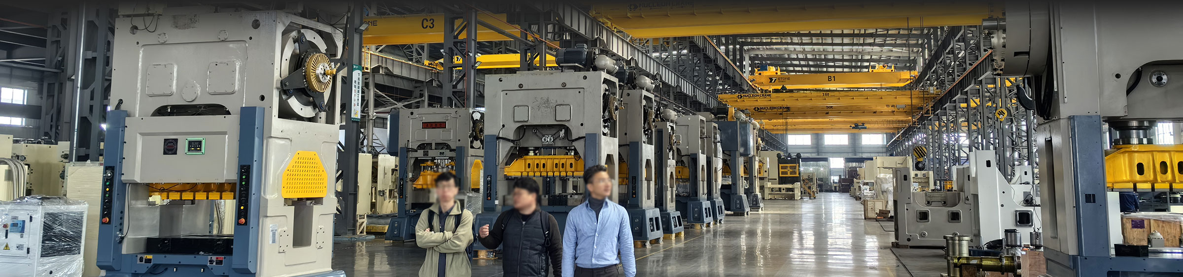
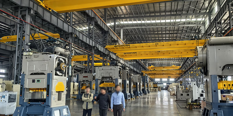
• Lateral feeding with reasonable side window space, wide-body double support connecting rod and lengthened guide rail design, strong antibiased load ability, multi-station automatic forging combined with stepping manipulator.
• Floating insert type clutch friction block design, friction block than small pressure longer life, than the traditional structure replacement. The period is 2 to 3 times longer. Large braking torque, small braking Angle, simple and reliable structure and easy maintenance. Brake with a forced water cooling system, low temperature rise can achieve highspeed single operation.
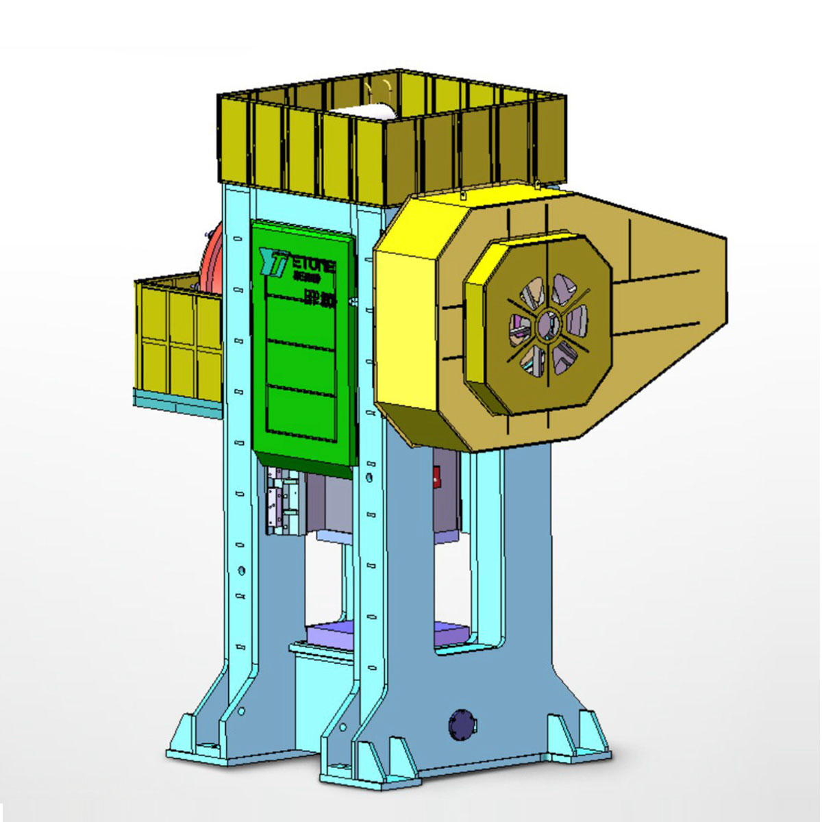
• The eight-sided guide rail design has high guidance accuracy and the forging quality has been improved.
• With anti-stuck mold structure design to provide customers with high added value products.
• Applicable forgings: disc, gear, gear blank, belt wheel, wheel shell, etc.;
Long shaft, gear with handle, wheel shaft, fork shaft, etc.; Special-shaped parts, such as steering, crankshaft, CAM, connecting rod, chain link, etc.
Technical parameters
Name |
Gauge |
EFP-400 |
EFP-650 |
EFP-800 |
EFP-1000 |
EFP-1300 |
tonnage |
on |
400 |
650 |
800 |
1000 |
1300 |
Unloaded continuous stroke number |
PM |
90~110 |
90~100 |
85~100 |
80~90 |
75~95 |
Slide stroke length |
mm |
160 |
200 |
220 |
250 |
260 |
Die height |
mm |
500 |
555 |
600 |
755 |
845 |
Slide adjustment |
mm |
8 |
10 |
10 |
10 |
12 |
Slide area (LRxFB) |
|
550x600 |
650 × 700 |
750 × 800 |
920 × 920 |
920 × 103 |
Bolster area (LRxFB) |
Xm |
550x600 |
700 × 800 |
800 × 900 |
1100 × 1050 |
950 × 1300 |
BoLster area thickness |
mm |
110 |
120 |
130 |
150 |
150 |
Upper ejector device |
Type |
|
Hydraulic/National Gas Law Capital |
Hydraulic/National Gas Law Tour |
Hydraulic/hydrogen law tour |
Hydraulic/gas law tour |
Hydraulic/National Gas Law Capital |
Ejector force/stroke |
on/mr |
4/50 |
6/30 |
6/50 |
10/30 |
10/30 |
Upper ejector device |
Type |
|
Hydraulic/Mechanical |
Hydraulic/Mechanical |
Hydraulic/Mechanical |
Hydraulic/Mechanical |
Hydraulic/Mechanical |
Ejector force/stroke |
ton/me |
6/16 |
0/16(50) |
2/18(50) |
20/20(50) |
20/30(50) |
Main motor power |
Kw |
30 |
37 |
45 |
55 |
90 |
Name |
Gauge |
EFP-1600 |
EFP-2000 |
EFP-2500 |
EFP-3150 |
EFP-4000 |
tonnage |
on |
1600 |
2000 |
2500 |
3150 |
4000 |
Unloaded continuous stroke number |
PM |
75~85 |
65~85 |
70~80 |
50~60 |
40~50 |
Slide stroke length |
mm |
300 |
300 |
320 |
340 |
360 |
Die height |
mm |
915 |
915 |
900 |
000 |
100 |
Slide adjustment |
mm |
15 |
20 |
22.5 |
25 |
28 |
Slide area (LRxFB) |
|
100 × 1000 |
180x1260 |
260 × 138 |
1300 × 130 |
460 × 1710 |
Bolster area (LRxFB) |
Xm |
1200 × 1200 |
1210 × 1530 |
1300 × 1700 |
1350 × 1300 |
1500 × 2050 |
BoLster area thickness |
mm |
180 |
200 |
220 |
240 |
250 |
Upper ejector device |
Type |
|
Hydraulic/Hydrogen Bomb Tour |
Hydraulic/hydrogen legal capital |
Hydraulic/Hydrogen Bomb |
Hydraulic/Hydrogen Bomb Tour |
Hydraulic/high gas bomb |
Ejector force/stroke |
on/mr |
10/30 |
10/40 |
10/30 |
16/48 |
20/52 |
Upper ejector device |
Type |
|
Hydraulic/Mechanical |
Hydraulic/Mechanical |
Hydraulic/Mechanical |
Hydraulic/Mechanical |
Hydraulic/Mechanical |
Ejector force/stroke |
ton/me |
24/37(50) |
30/40(50) |
40/44(80) |
48/50 |
60/52(200) |
Main motor power |
Kw |
110 |
160 |
185 |
220 |
315 |
The above technical parameters can be modifhed as required.
Upper and lower topping form and parameters can be designed according to customer

 Mobile: +86-15990568092
 Email: china_etone@163.com
 WhatsApp: +84 333 853 031
 Wechat: 15990568092
 Contact: Mr.Bao
 Addess: Yinzhou Distrist, Ningbo, China